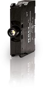
RAFIX 22 QR, LED element, screw terminal, without coupling, 230V, LED white
Article number: 5.00.070.086/0200

Technical data
|
General |
|
| Color | black |
| Luminous element color | white |
| Operating temperature, min. | -20 °C |
| Operating temperature, max. | 65 °C |
| Storage temperature, min. | -40 °C |
| Storage temperature, max. | 80 °C |
| illuminated | Yes |
| Luminous elements | LED |
| Packaging unit | 10 pcs. |
| Net weight | 14.4 g |
| Environment resistance |
IEC 60068-2-14
IEC 60068-2-30 IEC 60068-2-33 IEC 60068-2-78 |
| Shock resistance according to standard IEC 60068-2-27 | 50 g at 11 ms amplitude semi-sinusoidal |
| Vibration resistance according to standard IEC 60068-2-6 | 10 g at 40 - 500 Hz |
| Minimum order quantity (MOQ) | 10 pcs. |
| RoHS compliant | Yes |
| REACH compliant | Yes |
| Country of origin | HU |
|
Mounting dimensions |
|
| Outside dimension, length | 10 mm |
| Outside dimension, width | 46 mm |
| Outside dimension, height | 39.5 mm |
| Mounting depth | 56.4 mm |
|
Mechanical characteristics |
|
| Abisolierlänge | 8 mm |
| Wire end sleeve required | Ja |
| Terminal on the rear | Screw terminal |
| Fixing | Latching |
|
Electrical characteristics |
|
| Operating voltage of the luminous element, max. | 230 V |
| Voltage type | AC |
| Rated operating voltage | 230 V |
| Operating current of the luminous element, max. | 16 mA |
| Power loss | 3.68000 W |
| Maximum connection cross section | 1.5 mm² |
| Minimum connection cross section | 0.25 mm² |
Drawings
Description
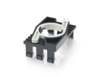
RAFIX control units are modular units consisting of several parts. In the RAFIX 22 QR family, they always consist of an actuating element, coupling, and switching element, or of a light attachment, coupling, and lamp socket. For assembly, the switching elements and lamp holders are first snapped into the coupling. Then this unit is snapped onto the actuating element or the signal lamp. To release, a bayonet lever must be actuated.
For illuminable actuators and indicator lights, please use a lamp socket / LED element as the middle element in the coupling.
Switching elements marked in different colors prevent confusion in the bearing and when connecting:
- 1/2 NC contacts = 1/2 red side cover
- 1/2 normally open contacts = 1/2 green side covers
- 1 NC and 1 NO contact = 1 red and 1 green side cover
- Silver contacts = housing base color black
- Gold contacts = housing base color gray
- Lamp socket and LED element = completely black
- The connections belonging to a pair of contacts are marked in color on the connection side and provided with contact identification numbers: 1-2 = NC contact, 3-4 = NO contact
Use according to UL:
RAFIX control devices are defined at RAFI as modular elements, consisting of an actuating element, if necessary a coupling and an individual contact or lighting unit.
Actuating elements (such as pushbuttons, emergency stop actuators, etc.) have the intended tactility, reset and function only when assembled with the appropriate switching elements.


