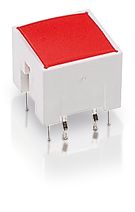
RACON 12 i, THT, 3.3 ± 0.6 N, bezel orange, 1 NO
Article number: 1.14.001.554/0000

Technical data
| Bezel color | orange |
| Luminous element color | orange |
| Operating temperature, min. | -40 °C |
| Operating temperature, max. | 80 °C |
| Storage temperature, min. | -50 °C |
| Storage temperature, max. | 85 °C |
| illuminated | Yes |
| Soldering time for manual soldering, max. | 5 sec |
| Soldering temperature for manual soldering | 350 °C |
| Soldering temperature for wave soldering | 260 °C |
| Soldering | Manual / wave |
| Solder heat resistance according to standard | DIN EN 60068-2-20 |
| Packaging unit | 45 pcs. |
| Net weight | 1.6 g |
| Operating life | 1,000,000 cycles |
| B10 | 1,300,000 cycles |
| MSL Moisture Sensitivity Level | 1 |
| Minimum order quantity (MOQ) | 270 pcs. |
| RoHS compliant | Yes |
| REACH compliant | Yes |
| Component material | Elastomer |
| Country of origin | HU |
| Outside dimension, length | 11.35 mm |
| Outside dimension, width | 11.35 mm |
| Outside dimension, height | 13.2 mm |
| Installation height | 9.7 mm |
| Grid, min. | 12.5 x 12.5 mm |
| Terminal on the rear | THT |
| Actuation function | momentary contact function |
| Operating force, min. | 3.3 ± 0.6 N |
| Contact function | 1 NO |
| Contact system |
Snap-action contact
SPST - Single Pole Single Throw |
| Contact material | Gold |
| Solderability | Yes |
| Switching travel | 0.34 ± 0.1 mm |
| Operating voltage of the luminous element, max. | 1.9 V |
| Rated voltage, min. |
|
| Rated voltage, max. | 35 V |
| Dielectric strength | 750 V |
| Operating current of the luminous element, max. | 50 mA |
| Rated current, min. |
|
| Rated current, max. |
|
| Rated power, max. | 1 W |
Drawings
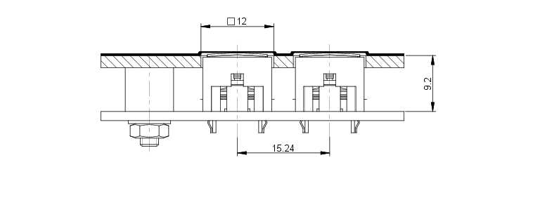
Dimensioned drawing

System drawing
PCB drawing

PCB drawing

Schematic diagram

Circuit diagram

Description
Flat data entry keyboards with RACON 12 i-elements should be constructed in a 15.24 mm grid. With this grid, strips of glue remain between the individual keys on the front panel. The overlay, which we recommend embossing above the key switches, can be glued onto these strips of glue. When using our RK 90 system design, we recommend 9 x 9 mm keycaps.
3D viewer
Downloads
CAD_3D_RAC12-11400155x
CP65 document

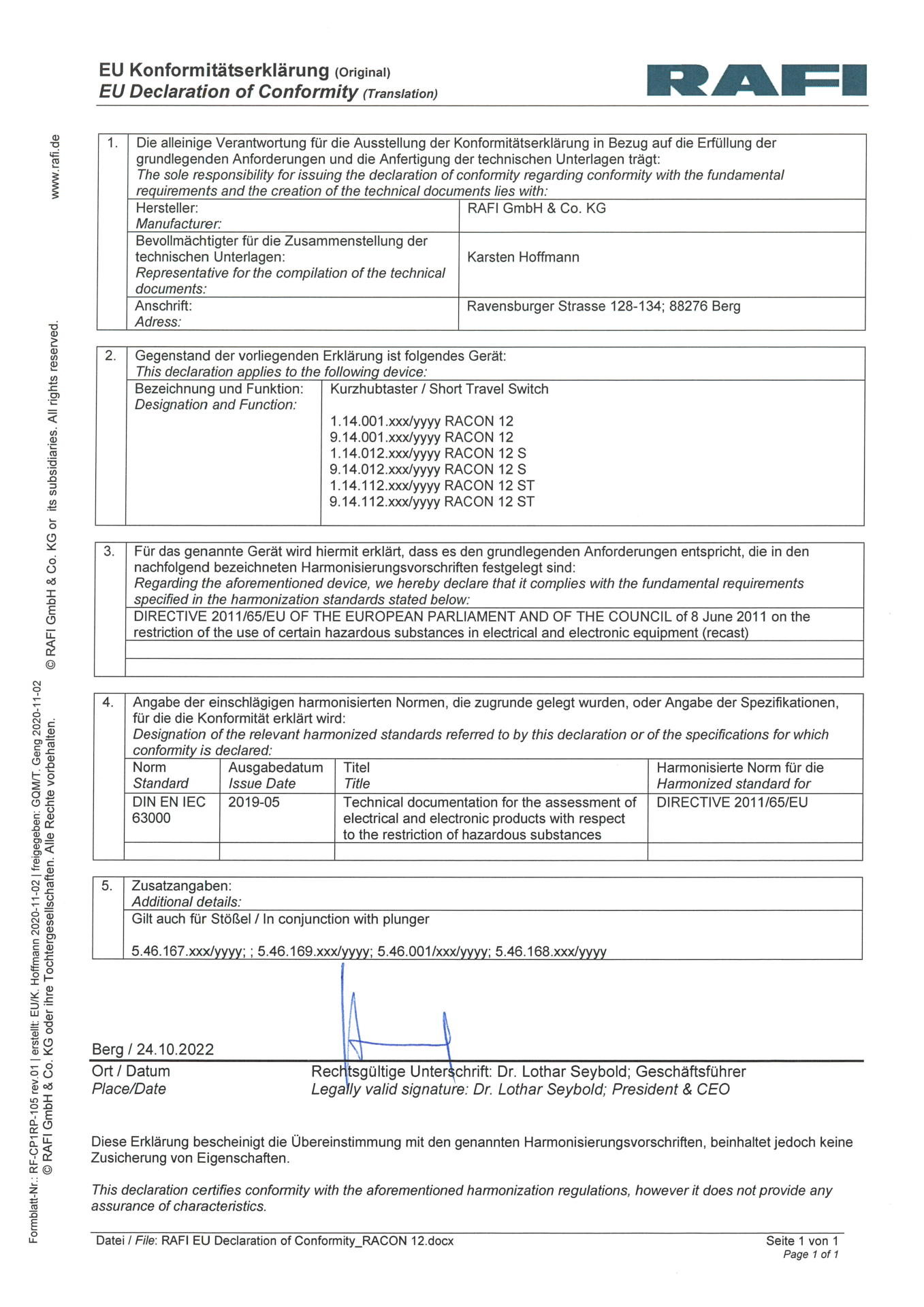
Declaration of conformity
POP document
RoHS
SVHC document
TSCA document

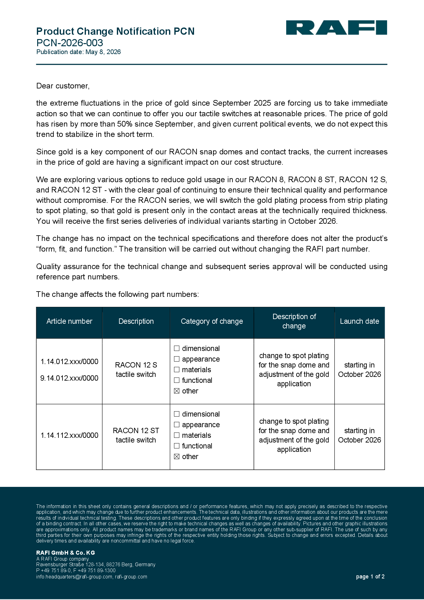
PCN product change notification
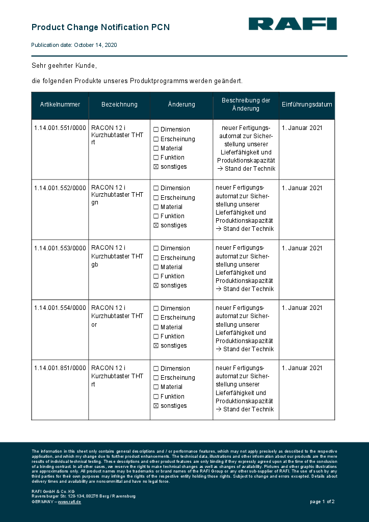
PCN product change notification